|
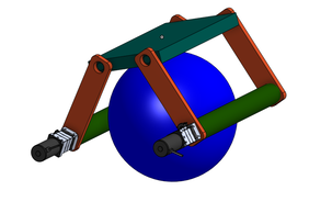
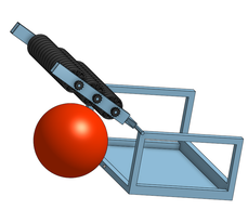
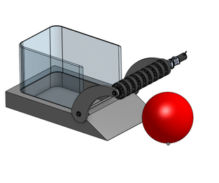
Introduction: This week, the team completed their second Preseason Design Challenge. The objective was to design a shooter that can shoot a 12 inch ball at a 7 foot high hanging target. Group 1- Piston Punch: (first picture) The "Piston Punch" mechanism is based around the ability to hit a target that is suspended 7ft in the air with a hard ball that has a diameter of 12 inches. To achieve this our shooter uses pneumatics. It uses one central piston with a large flat circle mounted between two arms that propel the ball forward once the piston is powered. The shooter is able to adjust its aim by changing its throwing angle. This angle is adjusted through the use of two gearboxes connected by a chain. When one of them runs, it causes the chain move the other gearbox. On the ends of the arms is a 11.5in by 11.5in piece of lexan with a 6.5in hole in the center of it, dubbed the "basket". In addition to this, it has 4 nine inch tall arms made of 1in by 1in pieces aluminum tubing that function to hold the ball in place wile the shot is lined up. Group 2- Crossbow Shooter: (second picture) This design has a crossbow-like system used to shoot the ball. There is a square frame that serves to guide the ball's directions and a carriage to hole the ball. Bow strings are connected from the front of the frame to the carriage to launch the ball. In order to create tension in the bowstrings, an Evo Shifting gearbox is used to pull back the carriage and create the tension necessary to launch he ball. Once it's ready to launch, using pneumatics the gearbox shifts into neutral and lets the carriage go free. There are a few cons with the design. The cost would be in the $400 range and there is a decent amount of aluminum tubing needed to make it. Along with tubing we would need the crossbow wires that connect to the carriage. It also requires multiple brackets and gussets to assemble. Electronically, there would be a need for a motor controller and encoder to know how far the carriage has been pulled back. Group 3- Catapult Launcher: (third picture) This design utilizes two pneumatic pistons to power a set of arms that launches a ball 7 feet into the air and toward a target. Pneumatic pistons are tube-like parts that have a slider inside and is extended and retracted using compressed air. The use of pistons allows each launch to be identical, increasing consistency and accuracy. The pressure from the pistons is able to create enough force to rotate the arm 90 degrees on its axle. When the arm reaches its maximum height, it will launch the ball with enough force to hit the target. 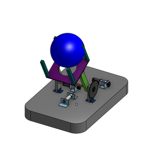  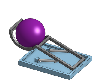
0 Comments
After a very successful 2018 season where we qualified for the World Championship, we are ready to kickoff a new season! This year we have 25 members, similar to last year. During this preseason, we have been refreshing old skills and training new members. This past week, our Robot Leads assigned the team with a Design Challenge. The challenge is meant to prepare the team for our upcoming season. The team did a game analysis of the 2013 game, Ultimate Ascent, to simulate what the team will be doing for the first few days after Kickoff. This week's challenge was to create an effective way to pick up a 12in ball. The team broke off into 3 separate groups, each with a different design. Group One- Roller Intake (first picture): To hold the 12 inch ball, this group made a design with two parallel rotating rollers 14 inches in length and 2 inches in diameter. On the rollers will be gripped patches. The rollers will have pins going through them to connect to a hex shaft. The hex shaft will lead to a bag motor fastened to a bracket that holds the roller. About 2 inches from the roller on each bracket, there will be surgical tubing bridging across the opposite rollers acting to provide tension. The brackets will be connected to a base allowing them to rotate freely. The base will then be attached to the theoretical robot. To intake the ball the whole assembly would come above the ball. Then both rollers would rotate inwards sort of sucking up the ball to intake it. To out take, the rollers would rotate outwards. Group Two- 45 Degrees of Freedom (second picture): This group's design consists of two pivoting connection points to the robot frame. This has approximately 45 degrees of freedom. Two side plates hold a shaft with powered rotating wheels. These wheels will come in contact with the 12 inch ball, forcing it towards the robot. The reason for these degrees of freedom is so the entire intake can move with the changing height of the ball, to maintain constant contact with it. When the ball is pulled close enough to the robot, it is forced up a ramp into a containment well. The sides are protected by panels so the ball cannot roll out. Group Three- too many wheels (third picture): This design incorporates a roller assembly on a hinge connected to the robot. Three sets of numerous rollers are driven by an electric motor. As the rollers are lifted, the ball is able to be pulled under the roller assembly . The wheels on the intake will spin against the ball and push it into the robot for manipulation. The rollers continue spin to ensure that it will stay inside the robot and will not fall out.
|